NEW Nizo 2.7 Volt lightmeter power circuit

2.7 Volt lightmeter power board for Nizo super8 camera

Presenting the latest solution for a 2.7Volts regulator circuit, to create a permanent solution for powering the lightmeter of the Nizo 8xx/5xx/4xx family of super8 cameras. These cameras normally require 2 buttoncell batteries of 1.35V each, which are hard or nearly impossible to come by nowadays.

We developed a new solution, on a dedicated tiny printed circuit board (10mm x 10mm), with only 3 components. It can be connected to the main battery supply of the super8 camera, and it supplies a rock-solid, constant 2.7 Volt output voltage that can be connected to the light meter circuit.

The circuit is designed around a dedicated voltage regulator IC. Packaged in a small SMD design this IC allows for a very small board design. Complemented with 2 capacitors the circuit board is a mere 10mm x 10mm in size. As a result it allows easy placement into the button-cell light meter battery container.

See this video for explanation and example installation of the regulator board into a Nizo 801 Macro super8 camera:

installing the Digital Super8 Lightmeter Power Board in a Nizo Super8 camera

The board has GND (black wire soldered to pad) and Vin (red wire soldered to pad) inputs and one Vout 2.7Volt output (the camera 2.7V lightmeter wire (usually yellow in Nizo’s) can be soldered to it). The EN pad can be left unconnected.

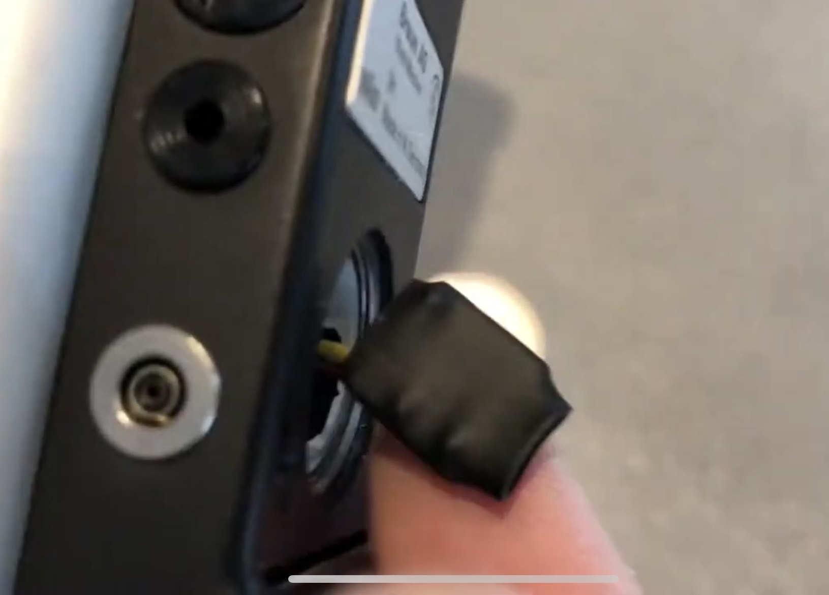
It is strongly advised to ensure that precautions are taken to isolate the board electronically to prevent short-cuts to ground. This is because the metal parts of the camera and the button-cell battery container cover are connected to ground. Using the provided shrink tube is advised.

Nizo lightmeter 2.7V voltage regulator

For the NEW 2.7 Volt Lightmeter Power Circuit, on a tiny 10mm x 10mm printed circuit board, go here: 

Loads of Braun Nizo super 8 camera owners, especially of the 400, 500 and 800 series have the problem of not being able to get their hands on 2 button cell batteries of 1.35V each. Together feeding the light meter circuitry with 2.7V. The original PX625 Mercury button cell batteries aren’t produced anymore, I guess for environmental reasons. They provided a 1.35V voltage. Nowadays the 625 batteries provide 1.5V.

The problem is that we have had quite some reports of owners using 2 cells of 1.5V each, thus providing 3Volts to the circuitry. This would give different light meter results so ideally one finds a way to provide 2.7V to the circuit without having to worry about button cell batteries in the Nizo.

There are quite a few solutions to the problem, such as using more environment friendly Weincell batteries (Zinc-Oxide), that do provide 1.35V but are quite expensive and tend to die rather quickly if not properly stored. Other solutions involve using Zener diodes and creating adapters from PX625 batteries that hold the zener diode and can house a smaller cell battery.

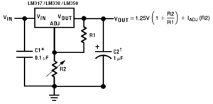
The solution proposed here is building a simple voltage regulator circuit existing of the LM317 voltage regulator IC, a 500 Ohm trimmer, a 220 Ohm resister, a 1mF electrolyte capacitor and a 100nF capacitor.  The circuit is shown below:

voltage-regulator

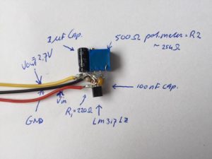
Soldered together the circuit looks like this:

nizo-lightmeter-voltage-regulator

Do connect this circuit to some power source like a 9V battery and adjust the trimmer such that you can measure 2.7V at the yellow output lead (use a multimeter).

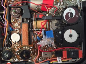
One way of adding the circuit to your Nizo camera is to first hot-glue all leads and solder to isolate them, open up the side of the camera (4 screws), solder GND and Vin and the 2.7V output to the correct contacts on the Nizo circuit board and place the circuit as shown below (Nizo 801 case but other cameras should be similar):

nizo-inside

When done correctly the side cover will just be able to still fit and you can screw it back on with the 4 screws. Do not forget to remove any remaining 625 button cell batteries from the camera or you can get failures.

Then, switch on the power of the Nizo and test the light meter by pressing the appropriate button and you will see a perfect indication of the meter on the number ‘8’  of the light meter.

Currently we are exploring a different way to add this circuit to the Nizo camera and that is to solder it together just tight enough that it will actually fit within the original button cell housing. One would have to take out the metal strip at the bottom of that housing, then 2 little holes are available. Through one of these holes one can put GND and Vin leads (have to be soldered to the right contact points within the camera, and the 2.7V output lead can be guided into the camera using the other hole. This method will be tested and instructions and pictures will be provided in a next post.